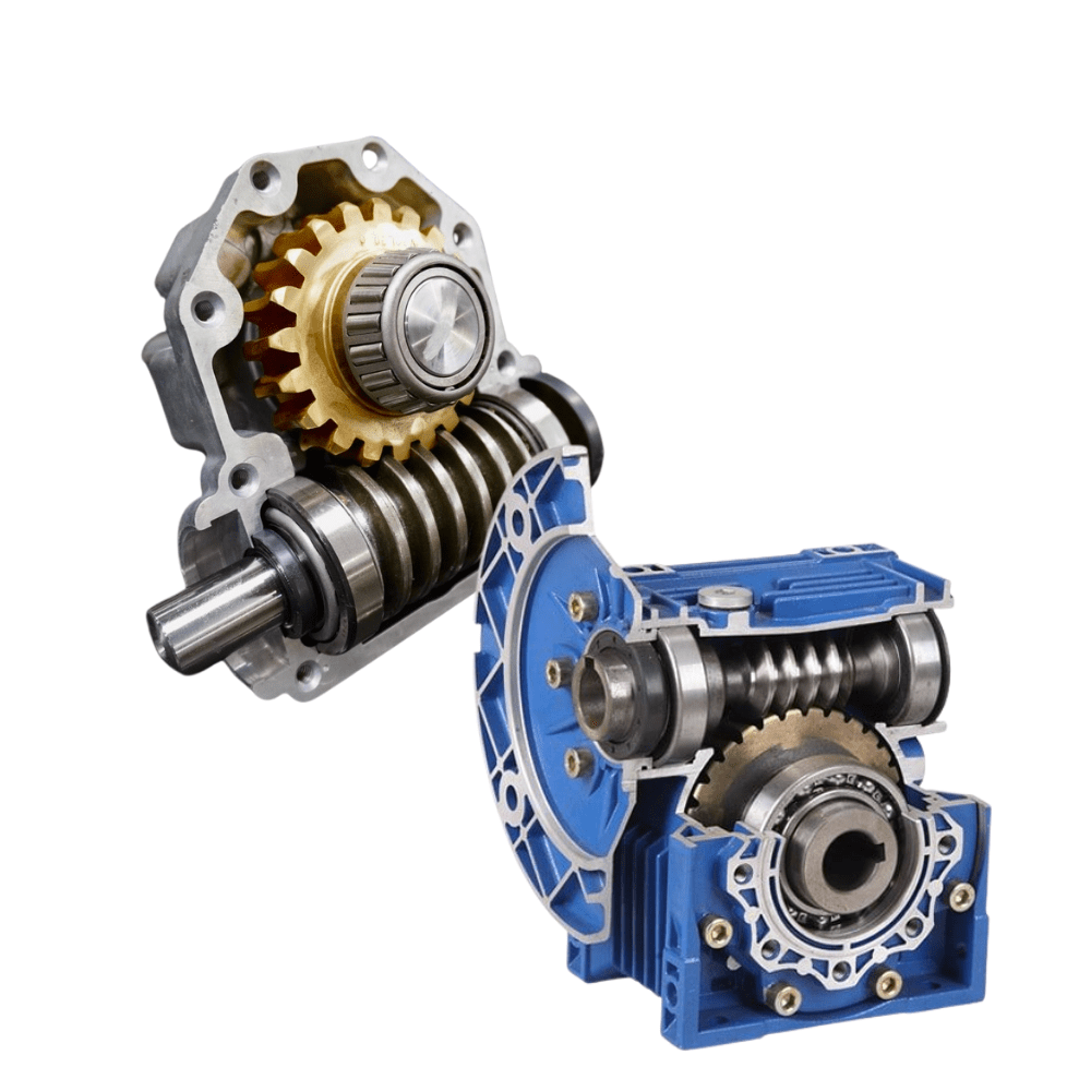
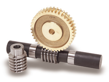
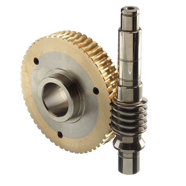
Product Description
| Module | 0.5, 0.8, 1, 1.25, 1.5, 2, 2.5, 3, 4, 5, 6 |
| Teeth Quantity | 10-150 teeth or customized |
| Number of Starts | 1, 2 or customzied |
| Twisting Direction | Left hand, right hand |
| Inner Bore |
3-200mm H7 or customized |
| Teeth Width |
5-200mm or customized |
| Outer Diameter,Hub Outside Diameter(mm) |
Customized |
| Material | C45 steel, Stainless steel, Plastic, Iron, steel… etc |
| Advance Angle(°) | 2°36′, 3°17′, 3°26′, 3°35′, 3°42′, 3°52′, 3°55′, 5°13′, 6°34′, 6°54′, 7°11′, 7°25′, 7°46′, 7°50′ |
| Torsional Angle(°) |
3°26′, 3°35′, 3°42′, 3°52′, 3°55′, 6°54′, 7°11′, 7°25′, 7°46′, 7°50′ |
1.Q:Are you trading company or manufacturer?
A: We are factory with more then 15years experience
2.Q: How long is your delivery time?
A: Generally it is 15-30days as we are Customized service we confirm with Customer
when place order
3.Q:Do you provide samples? ls it free or extra?
A: Yes we provide samples .for sample charge as per sample condition to decide free
or charged ,usually for not too much time used consumed machining process are free
4.Q:What is your terms of payment?
30% T/T in advance balance before shipment .Or as per discussion
5.Q: Can we know the production process without visiting the factory?
A:We will offer detailed production schedule and send weekly reports with digital
pictures and videos which show the machining progress
6.Q:Available for customized design drawings?
A: YesDWG.DXF.DXW.IGES.STEP. PDF etc
7.Q:Available for customized design drawings?
A: Yes ,we can CHINAMFG the NDA before your send the drawing
8.Q:How do you guarantee the quality?
A:(1) Checking the raw material after they reach our factory——
Incoming quality control(IQC)
(2) Checking the details before the production line operated
(3) Have a full inspection and routing inspection during mass production—
In-process quality control(IPQC)
(4) Checking the goods after they are finished—- Final quality control(FQC)
(5) Checking the goods after they are finished—–Outgoing quality control(QC)
(6)100% inspection and delivery before shipment.
| Application: | Motorcycle, Car, Vehicle |
|---|---|
| Hardness: | Hardened Tooth Surface |
| Manufacturing Method: | Cast Gear |
| Toothed Portion Shape: | Spur Gear |
| Material: | Steel |
| Type: | Worm And Wormwheel |
| Samples: |
US$ 2/Piece
1 Piece(Min.Order) | |
|---|
| Customization: |
Available
| Customized Request |
|---|

What are the advantages and disadvantages of using a worm gear?
A worm gear offers several advantages and disadvantages that should be considered when selecting it for a specific application. Here’s a detailed explanation of the advantages and disadvantages of using a worm gear:
Advantages of using a worm gear:
- High gear reduction ratio: Worm gears are known for their high gear reduction ratios, which allow for significant speed reduction and torque multiplication. This makes them suitable for applications that require precise motion control and high torque output.
- Compact design: Worm gears have a compact design, making them space-efficient and suitable for applications where size is a constraint. The worm gear’s compactness allows for easy integration into machinery and equipment with limited space.
- Self-locking capability: One of the key advantages of a worm gear is its self-locking property. The angle of the worm thread prevents the reverse rotation of the output shaft, eliminating the need for additional braking mechanisms. This self-locking feature is beneficial for maintaining position and preventing backdriving in applications where holding the load in place is important.
- Quiet operation: Worm gears typically operate with reduced noise levels compared to other gear types. The sliding action between the worm and the worm wheel teeth results in smoother and quieter operation, making them suitable for applications where noise reduction is desired.
- High shock-load resistance: Worm gears have good shock-load resistance due to the sliding contact between the worm and the worm wheel teeth. This makes them suitable for applications that involve sudden or intermittent loads, such as lifting and hoisting equipment.
- Easy installation and maintenance: Worm gears are relatively easy to install and maintain. They often come as a compact unit, requiring minimal assembly. Lubrication maintenance is crucial for optimal performance and longevity, but it is typically straightforward and accessible.
Disadvantages of using a worm gear:
- Lower efficiency: Worm gears tend to have lower mechanical efficiency compared to some other gear types. The sliding action between the worm and the worm wheel teeth generates higher frictional losses, resulting in reduced efficiency. However, efficiency can be improved through careful design, quality manufacturing, and proper lubrication.
- Limited speed capability: Worm gears are not suitable for high-speed applications due to their sliding contact and the potential for heat generation. High speeds can lead to increased friction, wear, and reduced efficiency. However, they excel in low to moderate speed applications where high torque output is required.
- Heat generation: The sliding action between the worm and the worm wheel generates friction, which can result in heat generation. In high-load or continuous-duty applications, this heat buildup can affect the efficiency and longevity of the system. Proper lubrication and heat dissipation measures are necessary to mitigate this issue.
- Less suitable for bidirectional motion: While worm gears offer excellent self-locking capabilities in one direction, they are less efficient and less suitable for bidirectional motion. Reversing the direction of the input or output shaft can lead to increased friction, reduced efficiency, and potential damage to the gear system.
- Lower accuracy in positioning: Worm gears may have lower accuracy in positioning compared to some other gear types, such as precision gear systems. The sliding contact and inherent backlash in worm gears can introduce some degree of positioning error. However, for many applications, the accuracy provided by worm gears is sufficient.
- Potential for wear and backlash: Over time, the sliding action in worm gears can lead to wear and the development of backlash, which is the play or clearance between the worm and the worm wheel teeth. Regular inspection, maintenance, and proper lubrication are necessary to minimize wear and reduce backlash.
When considering the use of a worm gear, it’s essential to evaluate the specific requirements of the application and weigh the advantages against the disadvantages. Factors such as torque requirements, speed limitations, positional stability, space constraints, and overall system efficiency should be taken into account to determine if a worm gear is the right choice.

Can worm gears be used in both horizontal and vertical orientations?
Yes, worm gears can be used in both horizontal and vertical orientations. Here’s a detailed explanation of the suitability of worm gears for different orientations:
1. Horizontal Orientation: Worm gears are commonly used in horizontal orientations and are well-suited for such applications. In a horizontal configuration, the worm gear’s weight is primarily supported by the bearings and housing. The lubrication and load-carrying capabilities of the gear design are optimized for horizontal operation, allowing for efficient power transmission and torque generation. Horizontal worm gear applications include conveyor systems, mixers, mills, and many other industrial machinery setups.
2. Vertical Orientation: Worm gears can also be used in vertical orientations, although there are some additional considerations to address in such cases. In a vertical configuration, the weight of the worm gear exerts an axial force on the worm shaft, which can introduce additional load and affect the gear’s performance. To ensure proper operation in a vertical orientation, the following factors should be considered:
- Thrust load handling: Vertical orientations impose a thrust load on the worm gear due to the weight of the gear and any additional external loads. The gear design should be capable of handling and transmitting this thrust load without excessive wear or deformation. Proper bearing selection and lubrication are crucial to support the axial load and maintain optimal performance.
- Lubrication: Lubrication becomes even more critical in vertical worm gear applications. Adequate lubrication ensures proper lubricant film formation to minimize friction, reduce wear, and dissipate heat generated during operation. Careful consideration should be given to the lubricant type, viscosity, and lubrication method to ensure effective lubrication, particularly in the upper parts of the gear where lubricant distribution may be more challenging.
- Backlash control: In vertical orientations, gravity can cause the load to act on the gear in the opposite direction, potentially leading to increased backlash. Proper gear design, including tooth geometry and clearance adjustments, can help minimize backlash and ensure precise motion control and positional stability.
- Bearing selection: The choice of bearings becomes crucial in vertical worm gear applications. Thrust bearings or combinations of thrust and radial bearings may be required to handle the axial and radial loads effectively. Bearings with appropriate load-carrying capacities and stiffness are selected to ensure smooth operation and minimize deflection under vertical loads.
- Sealing: Vertical orientations may require additional sealing measures to prevent lubricant leakage and ingress of contaminants. Proper sealing and protection mechanisms, such as seals or gaskets, should be implemented to maintain the integrity of the gear system and ensure reliable operation.
In summary, worm gears can be utilized in both horizontal and vertical orientations. However, certain considerations related to thrust load handling, lubrication, backlash control, bearing selection, and sealing should be taken into account for vertical applications. By addressing these factors appropriately, worm gears can effectively transmit power and torque, whether in horizontal or vertical configurations.

How do you calculate the gear ratio of a worm gear?
Calculating the gear ratio of a worm gear involves determining the number of teeth on the worm wheel and the pitch diameter of both the worm and worm wheel. Here’s the step-by-step process:
- Determine the number of teeth on the worm wheel (Zworm wheel). This information can usually be obtained from the gear specifications or by physically counting the teeth.
- Measure or determine the pitch diameter of the worm (Dworm) and the worm wheel (Dworm wheel). The pitch diameter is the diameter of the reference circle that corresponds to the pitch of the gear. It can be measured directly or calculated using the formula: Dpitch = (Z / P), where Z is the number of teeth and P is the circular pitch (the distance between corresponding points on adjacent teeth).
- Calculate the gear ratio (GR) using the following formula: GR = (Zworm wheel / Zworm) * (Dworm wheel / Dworm).
The gear ratio represents the speed reduction and torque multiplication provided by the worm gear system. A higher gear ratio indicates a greater reduction in speed and higher torque output, while a lower gear ratio results in less speed reduction and lower torque output.
It’s worth noting that in worm gear systems, the gear ratio is also influenced by the helix angle and lead angle of the worm. These angles determine the rate of rotation and axial movement per revolution of the worm. Therefore, when selecting a worm gear, it’s important to consider not only the gear ratio but also the specific design parameters and performance characteristics of the worm and worm wheel.


editor by CX 2023-10-05
